
4 Wire Reverse Camera Wiring Diagram Pdf
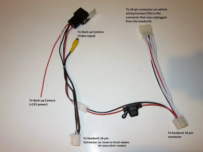
Installing a backup camera is simple when you have the right guide. A 4 wire reverse camera wiring diagram PDF shows exactly how to connect power, ground, video, and reverse trigger wires. This guide breaks down each step so you can finish the job safely and correctly. You will also find practical tips, common mistakes, and answers to frequent questions.
A backup camera makes reversing safer and easier. It helps you see obstacles, people, and tight spaces behind your vehicle. Many drivers want to install one themselves to save money and control the setup. The key to a smooth install is understanding the wiring. That is where a 4 wire reverse camera wiring diagram PDF becomes so useful.
This guide walks you through the basics of a reverse camera wiring diagram for a standard four-wire setup. You will learn what each wire does, how to connect it, and what to watch for during installation. We will also cover testing, mounting, and simple troubleshooting. If you want a clean install without confusion, this article will help you move step by step.
Key Takeaways
- Understand the four wires: power, ground, video signal, and reverse trigger make installation straightforward.
- Use a clear diagram: a 4 wire reverse camera wiring diagram PDF helps you avoid guesswork and wiring errors.
- Check wire colors: color standards vary by brand, so always confirm with your manual or diagram.
- Connect the reverse trigger correctly: this wire tells the head unit to show the camera view when you shift into reverse.
- Test before final mounting: verify power, video, and trigger function before drilling or trimming panels.
- Keep wires secure: use proper clips, loom, and grommets to protect cables from heat, moisture, and vibration.
- Seek help when needed: if your vehicle has complex electronics, consult a professional or your vehicle manual.
📑 Table of Contents
- What the Four Wires Do
- Why a 4 Wire Reverse Camera Wiring Diagram PDF Helps
- Common Wire Color Meanings
- How to Install a 4 Wire Reverse Camera Step by Step
- Testing and Troubleshooting Basics
- Mounting and Protection Tips
- Common Mistakes to Avoid
- When a Diagram Is Especially Useful
- Final Thoughts on the Install
What the Four Wires Do
Most basic backup cameras use four wires. Each wire has a clear job. When you understand these jobs, the install feels much less intimidating. A good reverse camera wiring diagram PDF usually labels each wire so you can match it to your camera and head unit.
1. Power Wire
The power wire sends electricity to the camera. This wire usually connects to a fused power source. In many installs, people use a reverse light circuit so the camera turns on only when needed. Some setups use constant power instead, depending on the camera and head unit design.
2. Ground Wire
The ground wire completes the electrical circuit. It usually connects to a clean metal point on the vehicle chassis. A solid ground matters a lot. Poor grounding can cause flickering video, weak signal, or no power at all.
3. Video Signal Wire
The video wire carries the image from the camera to your screen or head unit. This is often the most important connection for picture quality. A secure connection here helps you avoid static, snow, or a blank screen.
4. Reverse Trigger Wire
The reverse trigger tells your display to switch to the camera view. In many vehicles, this wire connects to the reverse light circuit. When you shift into reverse, the head unit receives the signal and shows the backup camera feed. Some systems handle this differently, so always check your specific diagram.
Why a 4 Wire Reverse Camera Wiring Diagram PDF Helps
Wiring can feel confusing if you are new to it. A 4 wire reverse camera wiring diagram PDF gives you a visual map. Instead of guessing where each wire goes, you can follow a clear layout. That saves time and reduces mistakes.
A good diagram also helps you compare your camera’s wiring to your vehicle’s setup. Some cars use different color codes or connector styles. A diagram helps you spot those differences before you cut or splice anything. If you want more detail on color standards, you can review a 4 pin reversing camera wiring colour codes guide for extra clarity.
Another benefit is confidence. When you can see the full path from camera to display, the install feels more manageable. You can plan your wire route, choose the right fuse, and decide where to tap into the reverse light circuit. That planning step matters because a neat install usually works better and lasts longer.
Common Wire Color Meanings
Wire colors can help, but they are not always the same across brands. Still, many systems follow general patterns. A reverse camera wiring diagram often shows these common associations:
- Red: power or ignition-switched power
- Black: ground
- Yellow or white: video signal
- Green or blue: reverse trigger, depending on the system
These colors are only a starting point. Always confirm the meaning with your camera manual or the diagram that came with your product. If your camera uses a different color code, the diagram should explain it clearly. When in doubt, trace each wire carefully instead of relying on color alone.
If you are comparing brands or setups, it can also help to look at related wiring topics. For example, some installers like to review a Pioneer reverse camera wiring diagram when they want to understand how a head unit handles the video input and trigger signal.
How to Install a 4 Wire Reverse Camera Step by Step
A careful install goes a long way. The goal is simple: connect the wires correctly, route them safely, and test everything before you finish the trim work. Here is a practical order you can follow.
Step 1: Gather Your Tools
Before you start, collect the basics. You will usually need:
- Wire strippers and cutters
- Electrical tape or heat shrink tubing
- A fuse tap or appropriate fuse holder
- Screwdrivers and trim tools
- Multimeter or test light
- Cable clips or loom
Having the right tools makes the job cleaner and safer. It also helps you avoid damaged wires or loose connections.
Step 2: Plan the Wire Route
Think about where the camera will sit and where the display is located. The video cable should travel from the rear to the front without sharp bends or pinch points. Try to keep wires away from hot parts, moving components, and sharp metal edges.
A clean route also looks better and is easier to protect. If you need to pass wires through metal, use a grommet or protective sleeve. This reduces wear over time and helps prevent shorts.
Step 3: Connect Power and Ground
Start with power and ground. Connect the camera power wire to a suitable fused source. If you want the camera to activate with reverse gear, tapping the reverse light circuit is a common approach. Connect the ground wire to a clean metal surface. Remove paint or rust at the contact point if needed so the ground stays solid.
Good power and ground connections matter more than many people expect. If the camera behaves strangely, poor grounding is often part of the problem.
Step 4: Attach the Video Cable
Connect the video wire to the camera output and the display input. Make sure both ends are secure. A loose video connection can cause intermittent picture loss, which is frustrating when you are trying to reverse safely.
If your setup includes a head unit with a dedicated camera input, follow the unit’s instructions. Some displays need a specific input selection or channel setting before they show the camera feed.
Step 5: Wire the Reverse Trigger
Connect the reverse trigger wire to the appropriate signal source. In many cases, this means connecting to the reverse light circuit so the camera activates when the vehicle is in reverse. This step is important because it controls when the screen switches to the backup view.
If you are unsure about the trigger source, check your vehicle manual or the camera instructions. A wrong trigger connection can cause the camera to turn on at the wrong time or not activate at all.
Step 6: Test Before Closing Everything
Test the system before you reinstall trim or tighten mounts. Put the vehicle in reverse and check whether the display shows the camera feed. If your system uses a manual camera button, test that too. Confirm that the picture is clear and that the trigger works consistently.
This step is one of the most valuable habits in any install. It is much easier to fix a wiring issue now than after everything is put back together.
Testing and Troubleshooting Basics
Even with a good diagram, issues can happen. The good news is that many problems are simple to check. A 4 wire reverse camera wiring diagram PDF can help you compare what you see in the vehicle with what the diagram expects.
No Power to the Camera
If the camera does not turn on, check the fuse first. Then verify the power connection and ground point. A loose ground or a missing fuse is a common reason for a dead camera.
No Video on the Screen
If the camera has power but the screen stays blank, check the video cable. Make sure it is connected to the right input. Also confirm that the display is set to show the camera when reverse is selected.
Flickering or Poor Picture
Flickering can come from a weak ground, a loose connector, or interference along the wire route. Inspect each connection and tighten anything that feels loose. If the wire runs near strong electrical noise sources, try rerouting it a little.
Camera Does Not Activate in Reverse
If the picture works manually but not automatically, the reverse trigger may be the issue. Check the trigger wire connection and the reverse light circuit. Some vehicles need a specific tap point or a different signal source.
If you want a broader look at camera activation behavior, you may find it useful to read how to turn on backup camera for general setup ideas and activation tips.
Mounting and Protection Tips
Wiring is only part of the job. A good mount and proper protection help the camera last longer and work better. A reverse camera wiring diagram may focus on electricity, but the physical install matters just as much.
Choose a Solid Mounting Spot
Pick a location that gives a clear view without blind spots from the bumper or license plate hardware. Many cameras mount above the license plate or in the trunk handle area. The best spot depends on your vehicle and camera style.
Secure the Cable
Use clips, tape, or loom to keep the cable in place. Loose wires can rub against metal or vibration points over time. A secured cable is safer and cleaner.
Protect Against Moisture and Heat
Seal connections where needed and keep wires away from hot surfaces. If the camera sits outside the vehicle, make sure the housing and connectors are appropriate for outdoor use. Good protection reduces future problems.
If your install involves mounting hardware questions, you might also look at a 1 4 inch camera mount screw reference when choosing the right fastener for your setup.
Common Mistakes to Avoid
A few mistakes show up often during backup camera installs. Avoiding them can save time and prevent frustration.
- Assuming wire colors are universal: always verify each wire’s function instead of guessing.
- Skipping the test step: waiting to test until after reassembly makes fixes harder.
- Using a weak ground: a bad ground can cause video and power issues.
- Routing wires poorly: sharp edges, heat, and movement can damage cables.
- Forgetting the fuse: proper fuse protection helps protect your vehicle’s electrical system.
- Ignoring the head unit settings: some displays need input selection or camera activation settings adjusted.
A careful install is usually a simple install. When you slow down and check each connection, you reduce the chance of rework.
When a Diagram Is Especially Useful
Some installs are straightforward. Others are less so. A 4 wire reverse camera wiring diagram PDF is especially helpful when your vehicle has unusual wiring, when the camera uses non-standard colors, or when you are combining parts from different sources.
It also helps when you are working with a used camera or a generic setup. In those cases, the diagram can act like a cheat sheet. You can match labels, confirm the trigger path, and make sure the video line goes to the right place. That clarity is valuable, especially if you are doing the job on your own.
If you are comparing different camera connector styles, you may also find a 6 pin reversing camera wiring diagram useful for understanding how some systems expand beyond the basic four-wire layout.
Final Thoughts on the Install
A backup camera is one of those upgrades that can make daily driving easier and safer. The wiring does not have to be mysterious. With a clear 4 wire reverse camera wiring diagram PDF, you can understand the power line, ground line, video line, and reverse trigger line without guesswork.
Take your time, test as you go, and protect your wires once the connections are done. A neat install usually gives better results and fewer headaches later. Whether you are upgrading an older vehicle or adding a camera to a new project, the four-wire setup is a practical place to start.
If you want to keep learning about camera setups and related wiring topics, you can also explore guides like how to keep backup camera clean for maintenance tips that help your new install stay in good shape.
Frequently Asked Questions
How many wires does a basic reverse camera use?
A basic setup often uses four wires: power, ground, video signal, and reverse trigger. Some cameras use more connections, but four wires are common for simple installs.
What is the reverse trigger wire for?
The reverse trigger wire tells the display to switch to the camera view when the vehicle is in reverse. It usually connects to the reverse light circuit or another reverse signal source.
Can I install a backup camera myself?
Yes, many people install a basic backup camera themselves if they are comfortable with simple wiring. A clear diagram and careful testing make the job much easier.
Do wire colors mean the same thing on every camera?
No, wire colors can vary by brand and model. Always check the camera manual or diagram before connecting anything, because color alone is not always reliable.
Why is my backup camera not showing a picture?
The most common reasons are a loose video connection, a missing power source, or a display set to the wrong input. Check each connection and test the system again before assuming the camera is faulty.
Should I connect the camera to constant power or reverse power?
It depends on the camera and head unit design. Many installs use the reverse light circuit so the camera activates only in reverse, but some systems work better with constant power. Follow the diagram or manual for your specific setup.
=== CONCLUSION ===
A 4 wire reverse camera wiring diagram PDF makes the install process much clearer. Once you know how power, ground, video, and reverse trigger wires work together, the project becomes far less stressful. Take your time, verify each connection, and test the system before finishing the mount. With a careful approach, you can get a reliable backup camera setup that helps you reverse with more confidence every day.