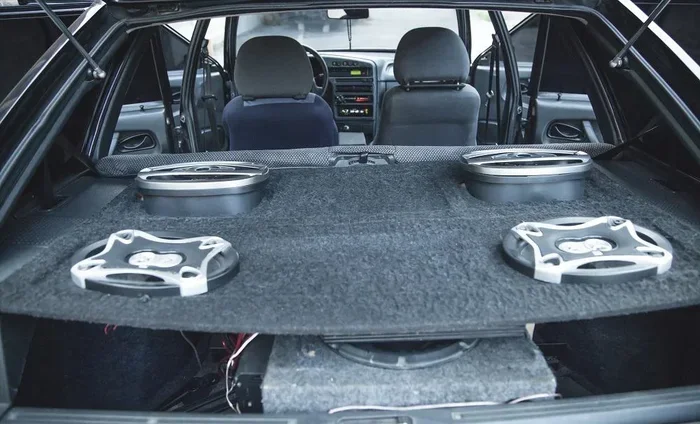
6 Speakers 4 Channel Amp Wiring Diagram

Want flawless sound from six speakers using a 4‑channel amp? This guide walks you through the complete 6 speakers 4 channel amp wiring diagram, from basic concepts to pro‑level wiring tricks. Follow our easy examples and avoid common mistakes for a clean, powerful install.
Key Takeaways
- Understand wiring basics: Learn series vs. parallel and why impedance matters.
- Choose the right amp: A 4‑channel amp can safely power six speakers when wired correctly.
- Follow the diagram: A step‑by‑step 6 speakers 4 channel amp wiring diagram prevents guesswork.
- Use quality components: Gauge‑appropriate wire, solid connectors, and a good ground are essential.
- Test before final install: Check polarity, continuity, and sound balance early.
- Protect your gear: Fuse placement and proper gain settings keep your amp and speakers safe.
- Future‑proof your system: Leave slack for upgrades and add a crossover if needed.
📑 Table of Contents
- Introduction: Why a 6 Speakers 4 Channel Amp Wiring Diagram Matters
- 1. Core Concepts: Impedance, Channels, and Power Distribution
- 2. Preparing Your Tools and Materials
- 3. Step‑by‑Step 6 Speakers 4 Channel Amp Wiring Diagram
- 4. Common Mistakes and How to Avoid Them
- 5. Enhancing Sound Quality: Crossovers and Tweeter Integration
- 6. Real‑World Example: Installing a 6 Speakers 4 Channel Setup in a 2015 Sedan
- Conclusion: Wire with Confidence
Introduction: Why a 6 Speakers 4 Channel Amp Wiring Diagram Matters
Imagine cruising down the highway, the bass thumps just right, the mids are crystal clear, and every door‑speaker sings in harmony. That feeling comes from a well‑planned wiring layout. When you have six speakers but only a 4‑channel amplifier, the wiring can get tricky. A solid 6 speakers 4 channel amp wiring diagram removes the guesswork, ensures each driver gets the power it needs, and protects your equipment from overload.
In this article we’ll break down the theory, walk you through the exact wiring steps, and share practical tips you can apply the same day you open your car’s dash. Whether you’re a first‑time installer or a seasoned hobbyist, you’ll finish with a clean diagram, confident connections, and booming sound.
1. Core Concepts: Impedance, Channels, and Power Distribution
What is Impedance?
Impedance is the speaker’s electrical resistance, measured in ohms. Most car speakers are 4 Ω, but 2 Ω and 8 Ω models exist too. An amp’s channel is designed to handle a specific impedance range—usually 2 Ω to 8 Ω. Exceeding this range can cause overheating or distortion.
Visual guide about 6 Speakers 4 Channel Amp Wiring Diagram
Image source: halohalo.space
Series vs. Parallel Wiring
When you wire speakers in series, you add their impedances (4 Ω + 4 Ω = 8 Ω). In parallel, you divide: 1 / (1/4 + 1/4) = 2 Ω. The 6 speakers 4 channel amp wiring diagram often uses a mix of both to keep each channel within the amp’s safe range.
Why a 4‑Channel Amp Can Power Six Speakers
A 4‑channel amp has four independent outputs. By bridging two channels together, you create a “dual‑channel” that can handle two speakers in parallel (or series) while still leaving two separate channels for the remaining speakers. The result: six speakers powered from four outputs without sacrificing power.
Internal Link Example
If you’re unsure which amp suits your setup, check out our recommended car amp for 6 speakers guide for specific models that play nicely with the wiring diagram.
2. Preparing Your Tools and Materials
Essential Gear
- 4‑channel amplifier (bridge‑capable)
- Six speakers (matching impedance)
- 16‑gauge speaker wire (or 14‑gauge for longer runs)
- Ring terminals, spade connectors, and a soldering iron
- Multimeter for continuity and polarity checks
- Inline fuse (30 A for 4 Ω, 40 A for 2 Ω loads)
- Wire loom or zip ties for neat routing
Safety First
Disconnect the car battery before you start. This prevents short circuits and protects the vehicle’s ECU.

Visual guide about 6 Speakers 4 Channel Amp Wiring Diagram
Image source: live.staticflickr.com
3. Step‑by‑Step 6 Speakers 4 Channel Amp Wiring Diagram
Step 1 – Plan the Layout
Draw a quick sketch of where each speaker sits (front left, front right, rear left, rear right, and two additional speakers—often tweeters or sub‑woofer passive radiators). Mark which amp channels you’ll bridge.
Visual guide about 6 Speakers 4 Channel Amp Wiring Diagram
Image source: i.pinimg.com
Step 2 – Bridge Channels A and B
Most 4‑channel amps allow you to bridge the left and right front channels (A + B) to power a pair of speakers in parallel. Connect the positive terminal of the first front speaker to the amp’s Channel A + and the negative to Channel A –. Do the same for the second front speaker using Channel B + and B –. Then, tie the two positive wires together and the two negative wires together. This creates a 2 Ω load (if both speakers are 4 Ω) that the bridged channel can handle.
Step 3 – Wire the Rear Speakers Individually
Use Channel C for the left rear speaker and Channel D for the right rear speaker. Keep these connections simple: positive to amp’s C +, negative to C –, and the same for D.
Step 4 – Add the Two Extra Speakers
These are often tweeters or small mids. You have two options:
- Option A – Series Pair: Connect the first extra speaker’s positive to Channel C +, its negative to the second speaker’s positive, and the second speaker’s negative to Channel C –. This yields an 8 Ω load, safe for most amps.
- Option B – Parallel Pair on a Bridged Pair: If your amp can handle 2 Ω on a bridged channel, you can parallel the two extra speakers on the already‑bridged front pair. This gives a total load of 2 Ω per speaker, delivering more power but demanding a robust amp.
Step 5 – Install the Fuse and Power Leads
Run a thick (+12 V) power cable from the battery to the amp’s power terminal, placing the inline fuse within 18 inches of the battery. Ground the amp to a clean metal point on the chassis, using a short ground strap.
Step 6 – Test the System
Reconnect the battery, turn on the amp, and play music at low volume. Use a multimeter to confirm each speaker’s polarity (positive to positive, negative to negative). Adjust the gain and crossover settings on the amp to match your speakers’ specifications.
Visual Summary
Below is a simplified visual representation of the wiring diagram (textual version):
Amp Channel A (bridged)  ──+── Speaker 1 (+)
                         │
                         +── Speaker 2 (+)
                         │
Amp Channel B (bridged)  ──–── Speaker 1 (–)
                         │
                         –── Speaker 2 (–)

Channel C ──+── Rear Left Speaker (+)
            │
            –── Rear Left Speaker (–)

Channel D ──+── Rear Right Speaker (+)
            │
            –── Rear Right Speaker (–)

Channel C (or Series) ──+── Extra Speaker 1 (+)
                         │
                         +── Extra Speaker 2 (+)
                         │
                         –── Extra Speaker 1 (–)
                         │
                         –── Extra Speaker 2 (–)
Adjust the diagram to match your specific amp’s bridging instructions. Always consult the amp’s manual for exact pinouts.
4. Common Mistakes and How to Avoid Them
Wrong Impedance Load
Connecting two 4 Ω speakers in parallel without bridging creates a 2 Ω load, which many amps can’t handle. Always verify the amp’s minimum impedance per channel before deciding on parallel or series.
Crossed Polarity
If one speaker’s positive wire is attached to a negative terminal, that driver will be out of phase, causing thin sound and cancellation. Use a multimeter to double‑check polarity before finalizing connections.
Insufficient Fuse Rating
Using a fuse that’s too low will blow it during normal operation; too high and you risk fire. Follow the amp’s recommended fuse size based on total load.
Neglecting Ground Quality
A loose ground causes hiss, pops, and intermittent power loss. Scrape away paint, use a star‑dialed bolt, and keep the ground wire short.
Internal Link Example
Need more detail on proper grounding? Our how to wire speakers to amp article covers grounding and fuse placement in depth.
5. Enhancing Sound Quality: Crossovers and Tweeter Integration
Why Use a Crossover?
A crossover splits the audio signal into frequency bands, sending lows to woofers and highs to tweeters. This prevents tweeters from receiving bass they can’t handle, extending their life and improving clarity.
Passive vs. Active Crossovers
- Passive: Installed between amp and speaker, no external power needed. Simple but less precise.
- Active: Powered unit placed before the amp, offers fine‑tuned frequency control. Ideal for high‑end installs.
Integrating Tweeters into the 6 Speakers 4 Channel Amp Wiring Diagram
Place a small passive crossover (e.g., 2 kHz high‑pass) in series with each tweeter. Connect the crossover’s input to the speaker output of the amp channel that feeds the tweeter, and the output to the tweeter’s terminals. This keeps the tweeter’s load within the amp’s safe range.
Practical Tip
Run a short 12‑inch high‑quality wire from the amp to the crossover, then to the tweeter. Keep the crossover away from high‑current power wires to avoid interference.
6. Real‑World Example: Installing a 6 Speakers 4 Channel Setup in a 2015 Sedan
Vehicle Overview
The 2015 sedan has factory door speakers (4 Ω) and a rear deck that can accommodate two additional 4 Ω speakers. The owner wants to add a pair of front‑door tweeters for a richer high‑end.
Chosen Components
- Alpine MRV-F300 4‑channel amp (bridgeable, 2 Ω min)
- Six 4 Ω speakers (factory doors + aftermarket rear)
- Two 4 Ω tweeters (installed in the front doors)
- Passive 2 kHz crossover for each tweeter
Wiring Steps Summarized
- Bridge front left/right channels (A + B) to power the two door speakers in parallel.
- Connect rear left speaker to Channel C and rear right to Channel D.
- Series‑wire the two tweeters and attach the series pair to Channel C (after the rear left speaker) using a small 8 Ω crossover to keep load safe.
- Install fuse, ground strap, and run power cable.
- Test each speaker, adjust gain, and set the amp’s low‑pass filter at 80 Hz for woofers, high‑pass at 2 kHz for tweeters.
Result
The sedan now delivers balanced mids, tight bass, and sparkling highs without any distortion. The owner reports a “concert‑hall” feel even at highway speeds.
Conclusion: Wire with Confidence
Mastering the 6 speakers 4 channel amp wiring diagram transforms a complicated install into a straightforward project. By respecting impedance, using the correct bridging method, and following our step‑by‑step guide, you’ll protect your gear, enjoy clean sound, and have the flexibility to upgrade later. Remember to test early, keep connections tidy, and always respect safety—your ears (and your wallet) will thank you.
Frequently Asked Questions
Can I use a 4‑channel amp without bridging to power six speakers?
Yes, but you’ll need to wire some speakers in series to keep each channel’s impedance within the amp’s safe range. Bridging simplifies the process and often yields more power.
What gauge wire should I use for a six‑speaker install?
For runs under 10 feet, 16‑gauge speaker wire is sufficient. For longer runs or higher‑power setups, step up to 14‑gauge to reduce resistance.
Do I need a separate amplifier for the tweeters?
Not necessarily. You can feed tweeters from the same amp channel using a high‑pass crossover, provided the total load stays within the amp’s specifications.
How do I know if my amp can handle a 2 Ω load?
Check the amp’s manual or specifications sheet. It will list the minimum impedance per channel and the minimum for bridged channels.
Is it safe to install the fuse near the battery?
Yes, the fuse should be within 18 inches of the battery to protect the power cable from short circuits.
Can I add a subwoofer to this 6 speakers 4 channel setup?
You can, but you’ll need a dedicated sub‑woofer channel or a separate mono amp. Adding a subwoofer to the same 4‑channel amp would require careful impedance calculations and likely a higher‑power amp.